
Swivelling motion sensor in round metal frame
- Directional Motion Detection
- Adjustable detection angle with left-right recognition
- Detection range of 7 meters with a 110° viewing angle
- Integrated light sensor
- LED indication upon motion or light trigger
The SEN04ML/RMW is an indoor motion detector, featuring an adjustable detector and is built into a metal frame with clamps for easy wall or ceiling installation. The SEN04ML/RMW has a range of 7 meters within an angle of 110°.
Frequently Asked Questions
-
How do you read an existing configuration?
This is a completely different procedure depending on the type of controller.
- For the CTD controllers this goes as follows:
In the SMIII via "File" or "Utilities / Setup / SD card", click on "Recover QDB from SD".
After confirmation you choose the name and location where the file should be saved. The zipped QDB file is then read from the SD card of the CTD and saved. With a positive answer to the question "Unzip and open restored QDB?", All data will then be immediately available. If the data you were still working on was not sent or saved, you will first receive a notification to do so.
- For a CTL controller follow the following procedure:
Because this controller does not yet have a large memory, only limited data can be recovered. Ao the names are abbreviated to 12 characters and serial numbers are not stored anywhere.
The first step is therefore to type in ALL serial numbers via SMII via "File / Modules". These 6-digit serial numbers can be found on every module (DIN rail, switch, detector, etc.). For the SWC0x switches, an extra option was provided to have them send their serial number via “Search for modules”.
When you then click on the "down arrow", you can read all this limited information.
-
Always use the latest software for configuration.
It is always recommended to use the most recent version. This version supports the newest modules and resolves all known bugs.
If, for example, you enter a serial number and the correct module information does not appear, you are likely not working with the most recent software.
A newer version will always be able to open the older files (.QDB) without data loss.
The latest version of the System Manager software, along with the user manual and version history, can be found in the knowledge center.
Technical info for installers
-
Function description
Module décentralisée, équipée d'un détecteur de mouvement avec angle de vue réglable (pour montage mural et plafond) et d'une cellule lumineuse intégrée. Le détecteur est monté dans un cadre en métal avec des ressorts qui permet un encastrement dans une paroi ou un plafond creux. Le SEN04ML/RMW est connecté de manière décentralisée au bus et alimenté par celui-ci. Le détecteur de mouvement a une portée d'environ 7 mètres avec un angle de 110 degrés. Le capteur de lumière est intégré dans le détecteur de mouvement.
Le détecteur de mouvement peut faire la distinction entre un mouvement venant de la droite ou de la gauche. Cela peut par exemple être utilisé pour distinguer entre entrer ou sortir dans les couloirs (le mouvement entrant ou sortant doit être suffisamment long pour permettre la distinction).
Le capteur de lumière détecte le niveau lumineux dans un espace; ces niveaux de lumière peuvent être utilisés pour déclencher des actions (allumer les lumières lorsque le niveau de lumière est inférieur à X, fermer les stores lorsque le niveau de lumière est supérieur à Y, etc.).
Via le logiciel de configuration Qbus, il est possible de configurer si une sortie est activée en fonction de la lumière, du mouvement ou d'une combinaison de ces données.
Au SEN04ML/RMW peuvent être directement connectées 4 sorties (uniquement bistables). Chaque sortie peut être activée par :
Avec les minuteries, il est possible de définir combien de temps la sortie doit rester activée.
La LED dans le module peut être configurée pour clignoter à intervalles réguliers lorsqu'un mouvement est détecté ou lorsqu'un niveau de lumière est atteint.
Chaque module possède un numéro de série unique (6 chiffres). Sur la base de ce numéro de série, le module peut être programmé via le logiciel Qbus.
-
Technical specifications
GENERAL SPECIFICATIONS:
- Power supply: le bus
- Ambient temperature:
Operating temperature: 10°C to 50°C
Storage temperature: -10°C to 60°C
- Maximum humidity level: 93%, no condensation
- Bus load: 15 mA at nominal voltage 13.8V.
- Maximum installation height: 2,000 meters.
PHYSICAL SPECIFICATIONS
- Enclosure: metal
- Protection rating: IP20, EN 60529
- Dimensions:
Diameter of cover plate 80mm
Depth: 65mm
- Bore diameter minimum 55mm, maximum 70mm
- Weight: approximately 0.15 kg
ELECTRICAL PROTECTION
- Bus: 13.8VDC low voltage in accordance with EN60950 – 1: 2006
CE
- In compliance with EMC and low voltage regulations. The module complies with EN 61000-4-2 and 50090-2-2.
-
Sizing
![SEN04 MLRMW Dimensionering]()
-
Explanation of symbols
![Symbool dubbele isolatie 229x50 fit 300dpi]()
Equipment where protection against the risk of electric contact is not only based on basic insulation but also on additional protection such as double insulation or reinforced insulation. There is no possibility for grounding.
![Symbool gevaar aandachtig lezen 229x50 fit 300dpi]()
Before connecting the device, it is mandatory to read the manual of the respective product. ISO7000-0434
![Symbool gevaarlijke spanning 229x50 fit 300dpi]()
Power supply connection (230V) to the power supply connector. IEC 60417-5036
![Symbool CE keuring 229x50 fit 300dpi]()
CE conformity. All declarations of conformity are available upon request.
-
Warranty provision
Standard Warranty Period: 2 years from delivery date. The warranty is no longer valid if the module has been opened! Defective modules should be sent without seal along with a description of the defect to our service department:
QBUS N.V. Joseph Cardijnstraat 19, 9420 Erpe-Mere, Belgium
T +32 53 60 72 10 - F +32 53 60 72 19
Email: [email protected]


General
-
Safety regulations
Read the complete manual before installing the module and activating the system.
CAUTION
- The module must be installed, started, and maintained by a certified electrical installer in accordance with the applicable legal regulations of the country.
- The module has an IP65 rating = water-resistant. When used outdoors, it is recommended to place the module under a canopy.
- The module must not be opened. The warranty will be void if the module is opened!
Installation and wiring
-
Installation
Install the SEN04MW/RMW in a hole in a hollow wall or ceiling by simultaneously pressing both springs. Connect the bus cable to the connector on the back of the module.
Adjust the viewing angle by orienting the module's sphere (sensor). The red LED visible in the sphere at regular intervals indicates the presence of light and/or motion (as configured via the Qbus configuration software).
THE MODULE MUST BE MOUNTED IN A WAY TO ENSURE MAXIMUM RANGE OF THE SENSOR'S VIEWING ANGLE; AND NOT NEAR A HEATING OR COOLING APPLIANCE.
-
Power supply
The SEN04ML/RMW is powered via the bus.
IMPORTANT: THE BUS MUST NEVER COME INTO CONTACT WITH THE GROUNDING OR A LIVE CONDUCTOR!
(DIS)CONNECT MODULES ONLY WHEN THE BUS IS POWERED DOWN.
-
Bus connection
It is recommended to use the Qbus cable or any other cable with a minimum of 2 conductors of 1mm² as the bus cable. The green shielded EIB cable can also be used if the conductors are paired to achieve a minimum cross-section of 2 x 1mm².
Each modules has an unique serial number. By this number the System Manager recognizes the modules.
This is completely explained in our knowledge center.
The following screen is displayed when the serial number was entered or selected.
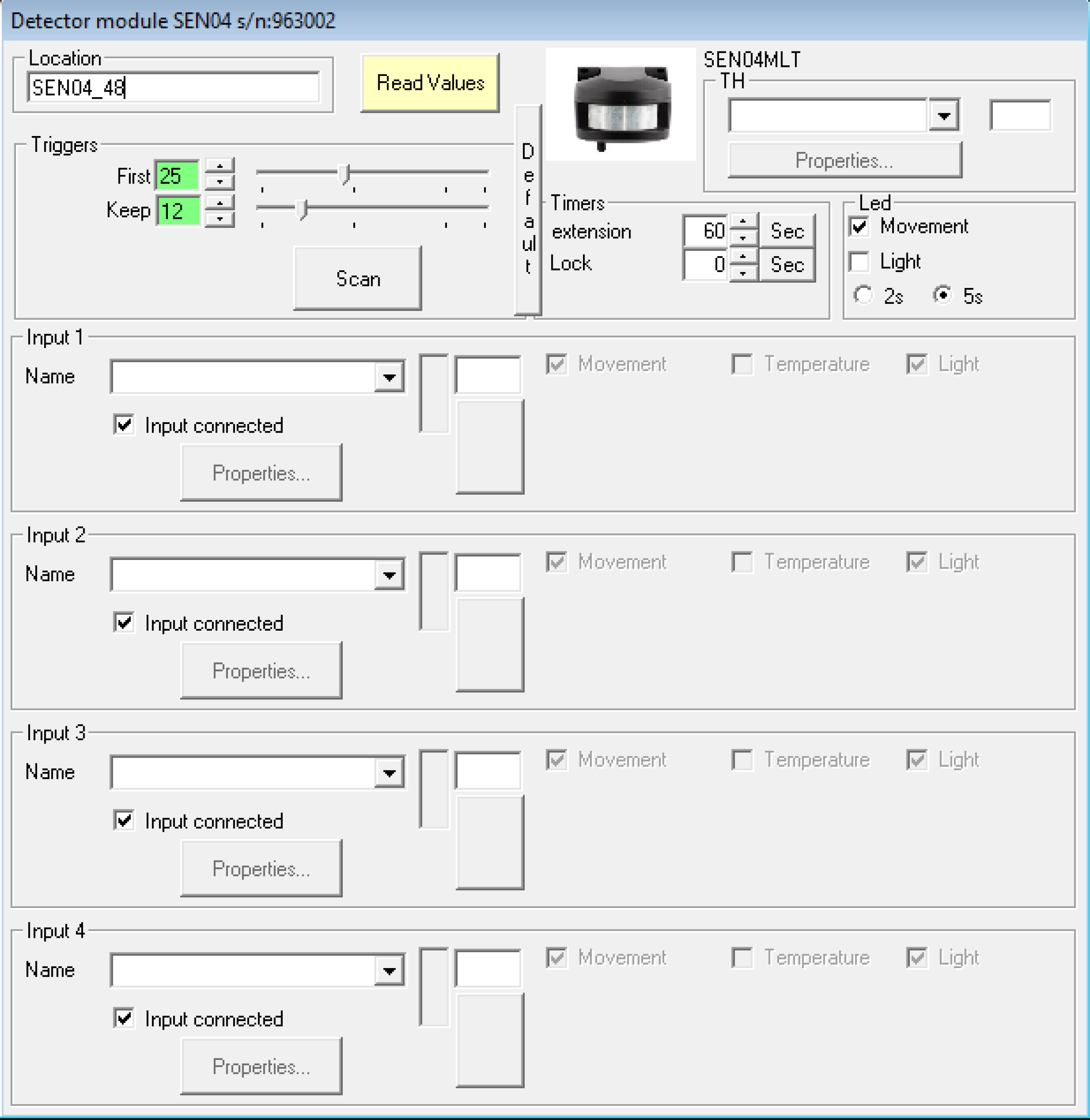
ATTENTION!!!! : Only bistable type inputs can be controlled
- Triggers
The parameters of these fields are for setting the trigger sensitivity.
First: The level of motion must be higher than this set value to activate the I/O
Keep: The level of motion must be higher than this set value to maintain the state of the I/O.
Scan: A visualization of the detector is shown. The I/O will be activated when the level is higher than the green line and will time out if it stays below the yellow line:

LED field
You can select when the built-in red LED will be activated, based on the motion or light level or both.
"Timers" field
Extension: Corresponds to the extension of the period during which the I/O’s remain activated. The smallest possible timer value is 2 seconds.
Lock:
This sets the period of time the sensor will lock (and will not activate the I/O) after the I/O has become inactive.
Fields "Input x"
Movement: Activation of the sensor due to the movement.
Light:
If ‘Movement’ is checked, this additional option "light", will only activate the I/O if the light level is lower than the set value. This is useful to prevent the I/O from being activated during the day. The threshold value can be set with the buttons or slider. When only this option is checked (without ‘Movement’), the I/O will only be activated if the measured light value is HIGHER than the set threshold value.
The current light value will be displayed with a yellow or black bar via the “Read values” button. When the threshold value is in the colored bar, the I/O will be activated.