
Motion detector with Bticino design
- Adjustable indoor motion detector with built-in light sensor
- Compatible with Bticino cover frame (not included)
- Range of 7 meters with a detection angle of 110°
- Color: Light white
Adjustable indoor motion detector with a built-in light sensor. The MDI01/N is compatible with Bticino cover frame (not included). The MDI01/N has a range of 7 meters at an angle of 110°.
Frequently Asked Questions
-
How do you read an existing configuration?
This is a completely different procedure depending on the type of controller.
- For the CTD controllers this goes as follows:
In the SMIII via "File" or "Utilities / Setup / SD card", click on "Recover QDB from SD".
After confirmation you choose the name and location where the file should be saved. The zipped QDB file is then read from the SD card of the CTD and saved. With a positive answer to the question "Unzip and open restored QDB?", All data will then be immediately available. If the data you were still working on was not sent or saved, you will first receive a notification to do so.
- For a CTL controller follow the following procedure:
Because this controller does not yet have a large memory, only limited data can be recovered. Ao the names are abbreviated to 12 characters and serial numbers are not stored anywhere.
The first step is therefore to type in ALL serial numbers via SMII via "File / Modules". These 6-digit serial numbers can be found on every module (DIN rail, switch, detector, etc.). For the SWC0x switches, an extra option was provided to have them send their serial number via “Search for modules”.
When you then click on the "down arrow", you can read all this limited information.
-
Always use the latest software for configuration.
It is always recommended to use the most recent version. This version supports the newest modules and resolves all known bugs.
If, for example, you enter a serial number and the correct module information does not appear, you are likely not working with the most recent software.
A newer version will always be able to open the older files (.QDB) without data loss.
The latest version of the System Manager software, along with the user manual and version history, can be found in the knowledge center.
Technical info for installers
Each modules has an unique serial number. By this number the System Manager recognizes the modules.
This is completely explained in our knowledge center.
The following screen is displayed when the serial number was entered or selected.
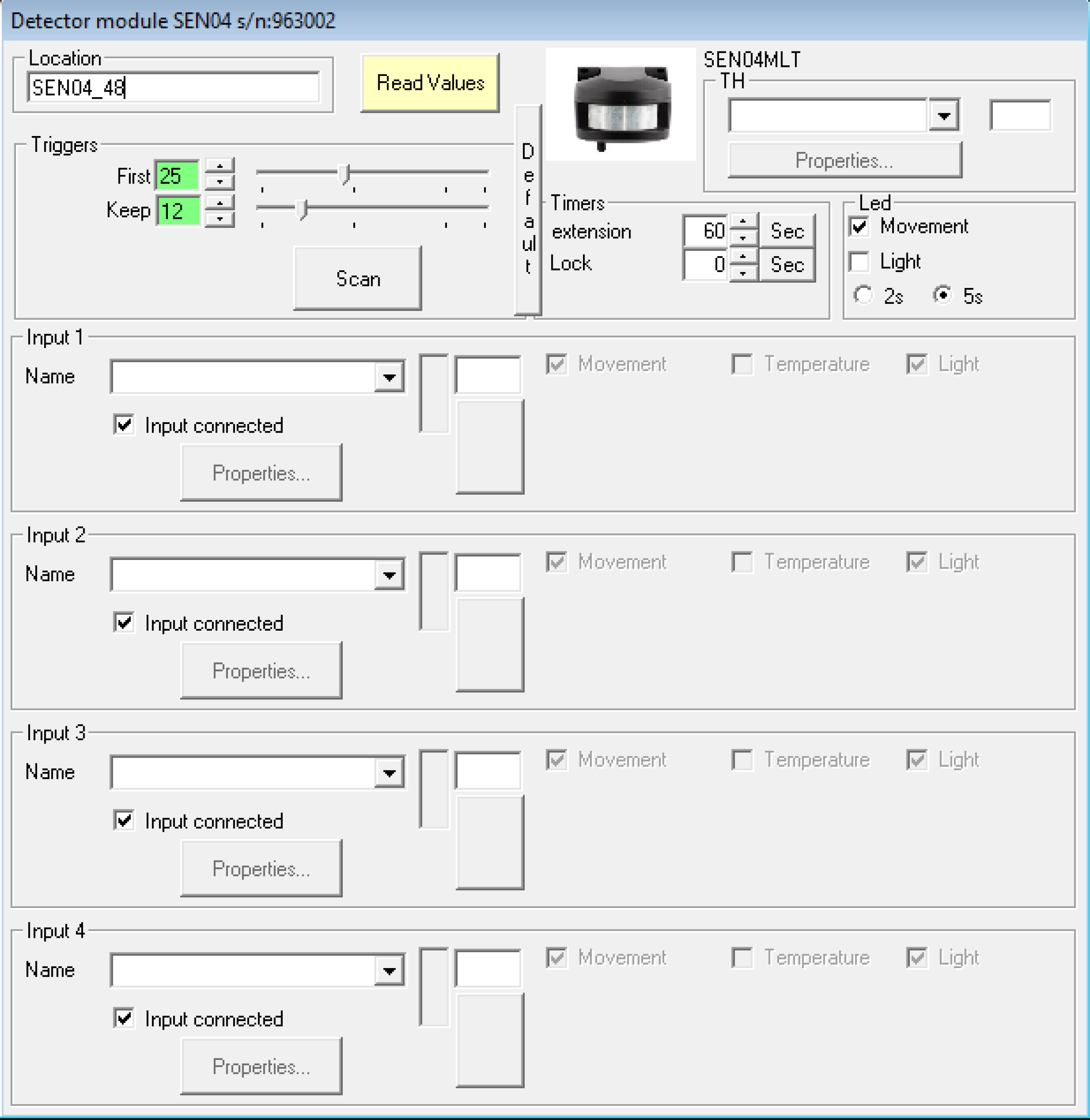
ATTENTION!!!! : Only bistable type inputs can be controlled
- Triggers
The parameters of these fields are for setting the trigger sensitivity.
First: The level of motion must be higher than this set value to activate the I/O
Keep: The level of motion must be higher than this set value to maintain the state of the I/O.
Scan: A visualization of the detector is shown. The I/O will be activated when the level is higher than the green line and will time out if it stays below the yellow line:

LED field
You can select when the built-in red LED will be activated, based on the motion or light level or both.
"Timers" field
Extension: Corresponds to the extension of the period during which the I/O’s remain activated. The smallest possible timer value is 2 seconds.
Lock:
This sets the period of time the sensor will lock (and will not activate the I/O) after the I/O has become inactive.
Fields "Input x"
Movement (right/left): Activation of the sensor due to the movement reaching the detection range from the left or right side. If you choose both, the sensor will scan both the left and right sides.
Light:
If ‘Movement’ is checked, this additional option "light", will only activate the I/O if the light level is lower than the set value. This is useful to prevent the I/O from being activated during the day. The threshold value can be set with the buttons or slider. When only this option is checked (without ‘Movement’), the I/O will only be activated if the measured light value is HIGHER than the set threshold value.
The current light value will be displayed with a yellow or black bar via the “Read values” button. When the threshold value is in the colored bar, the I/O will be activated.