Qbus weather station
- Automatically controls sun shading, roller shutters, or lighting based on local temperature, rain, wind, and brightness.
- Advanced wind sensor: Detects light gusts and slanted winds
- Heated rain sensor prevents false readings
- Easy connection to the Qbus system via RS485 and the SER485/APIEN DIN-rail module
- Visualization via the Qbus Control app and cloud
The Qbus weather station measures temperature, precipitation, wind speed, and brightness (in eastern, western, and southern directions). Prevent overheating by automatically closing screens on the sunny side, or close your sunshade if there is too much wind. Visualize all this on Qbus Control.
Frequently Asked Questions
-
How do you read an existing configuration?
This is a completely different procedure depending on the type of controller.
- For the CTD controllers this goes as follows:
In the SMIII via "File" or "Utilities / Setup / SD card", click on "Recover QDB from SD".
After confirmation you choose the name and location where the file should be saved. The zipped QDB file is then read from the SD card of the CTD and saved. With a positive answer to the question "Unzip and open restored QDB?", All data will then be immediately available. If the data you were still working on was not sent or saved, you will first receive a notification to do so.
- For a CTL controller follow the following procedure:
Because this controller does not yet have a large memory, only limited data can be recovered. Ao the names are abbreviated to 12 characters and serial numbers are not stored anywhere.
The first step is therefore to type in ALL serial numbers via SMII via "File / Modules". These 6-digit serial numbers can be found on every module (DIN rail, switch, detector, etc.). For the SWC0x switches, an extra option was provided to have them send their serial number via “Search for modules”.
When you then click on the "down arrow", you can read all this limited information.
-
Always use the latest software for configuration.
It is always recommended to use the most recent version. This version supports the newest modules and resolves all known bugs.
If, for example, you enter a serial number and the correct module information does not appear, you are likely not working with the most recent software.
A newer version will always be able to open the older files (.QDB) without data loss.
The latest version of the System Manager software, along with the user manual and version history, can be found in the knowledge center.
Control
Operations via Qbus Control
-
Weather station
![Weather station]()
This I/O shows you what the weather currently looks like, based on the measurements from the weather station.
At the bottom, you see:
- The current temperature
- The current wind speed
- The value of the rain sensor
- The value of the light measurement
- The status of the twilight
You cannot control the outputs of this module via Qbus Control
With the graph icon in the top right corner, you can view the historical data.


Technical info for installers
-
Function description
With the Qbus weather station, it is possible to initiate actions based on local weather conditions. Additionally, Qbus provides various options for visualizing the measurements. The weather station comprises several components and features different sensors. Applications range from operating shutters, sun blinds, awnings, automatic irrigation, lighting at dusk...
Qbus weather station components included in the delivery:
1. Qbus SER485 Interface (SER485/APIEN), DIN-rail module, suitable for connecting the Qbus installation to the RS485 application of an Elsner weather station type P03 RS485 or P04 RS485
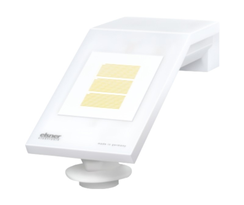
2. Weather station type Elsner P04/3-RS485 basic
3. Power supply 24VDC.
4. Connection cable +/-10m with 4-pin screw connector
5. Surface-mounted junction box (IP 55, not weatherproof)
6. Clamping ring Ø 40-60 mm for mounting on a pole
7. Stainless steel screws with round head 4mm × 50mm and plugs 6mm × 30mm for wall mounting.
The SER485/APIEN is the interface that connects the Qbus bus with the weather station's RS485 bus, and it has a unique serial number that is entered during configuration in the configuration software Systemmanager III. All programmed data is internally stored in permanent memory. The outdoor unit/weather station features the following sensors:
- Brightness measurement with 3 separate lux measurements: East, South, and West. Recognition of dusk/dawn.
- Wind measurement: The wind strength measurement is electronic, making it silent and reliable, even in hail, snow, and sub-zero temperatures. Even turbulent air and anabatic winds (slope winds) near the weather station are recorded.
- Temperature measurement
- Heated precipitation sensor: No false alarms due to mist or dew. Dries quickly after precipitation has stopped.
-
Technical specifications
General specifications SER485/APIEN
- Power supply: the bus
Ambient temperature:
Operating temperature: 10°C to 50°C
Storage temperature: -10°C to 60°C
- Maximum humidity: 93%, no moisture condensation
- Bus power supply: 30 mA at nominal 13.8 V
- Max. installation height: 2,000 meters.
SER485/APIEN Connections
- The maximum distance, of the signal between the SER485/APIEN and the weather station, is 1000m. However, the maximum distance between the 24VDC power supply and the weather station is 50m!
Physical specifications SER485/APIEN:
- Enclosure: plastic, self-extinguishing according to UL94
- Protection rating: IP20, EN60529
- Installation: fast mounting on DIN-rail, width 2 modules
- Dimensions (H x W x L): 62 mm x 90 mm x 36 mm
- Weight: approximately 0.072 kg
CE:
- Bus: 13.8 VDC low voltage
- Non-toxic, in accordance with WEEE/RoHS
- Complies with EN 60730-1:2000-11 +A11 2002
General specifications Elsner weather station P04-RS485
- Power supply: 24VDC +/-10%
- Maximum power consumption 100mA (24VDC)
- Operating temperature and measurement range: -30°C to 50°C
- Storage temperature: -30°C to 70°C
- Temperature measurement accuracy 0.1°C
- Wind sensor measurement range: 0 to 35m/s
- Wind measurement accuracy: +/-15%
- Lux measurements range: 0 to 99000lux
- Lux measurement resolution: 1 lux to 300 lux, 2 lux to 1000 lux, 25 lux to 99,000 lux
- Lux measurement accuracy: between 30 and 30000lux +/-15%
Elsner P04-RS485 Connections
- The maximum distance, of the signal between the SER485/APIEN and the weather station, is 1000m. However, the maximum distance between the 24VDC power supply and the weather station is 50m!
- Up to five SER485/APIEN can be connected in a tree structure, in parallel. If more interfaces need to be connected, you can contact Qbus Support for a suitable solution. This way, you can connect more Qbus installations to the same weather station.
Physical specifications Elsner P04-RS485:
- Enclosure: White translucent plastic housing UL94
- Dimensions: +/- 62 x 71 x 152 (W × H × D, mm)
- Protection rating: IP44
- Installation: on the wall via 2 screws and plugs, on a pole using a tension band.
- Dimensions (H x W x L): 62 mm x 90 mm x 36 mm
- Weight of weather station incl. mounting: +/- 90g
- The product is compliant with the provisions of the EU directives
-
Sizing
-
Expanation of symbols
![Symbool dubbele isolatie 229x50 fit 300dpi]()
Equipment where protection against the risk of electric contact is not only based on basic insulation but also on additional protection such as double insulation or reinforced insulation. There is no possibility for grounding.
![Symbool gevaar aandachtig lezen 229x50 fit 300dpi]()
Before connecting the device, it is mandatory to read the manual of the respective product. ISO7000-0434
![Symbool gevaarlijke spanning 229x50 fit 300dpi]()
Power supply connection (230V) to the power supply connector. IEC 60417-5036
![Symbool CE keuring 229x50 fit 300dpi]()
CE conformity. All declarations of conformity are available upon request.
-
Maintenance
Attention! Risk of injuries caused by automatic controls. An automation system can activate moving parts and thereby endanger people.
Always interrupt the power supply when working on the weather station, and ensure necessary safety measures.
The device should be checked for dirt accumulation twice a year or regularly and cleaned if necessary.
In the event of excessive dirt accumulation, the sensor may no longer function properly. -
Warranty Provision
Standard Warranty Period: 2 years from delivery date. The warranty is no longer valid if the module has been opened! Defective modules should be sent without seal along with a description of the defect to our service department:
QBUS N.V. Joseph Cardijnstraat 19, 9420 Erpe-Mere, Belgium
T +32 53 60 72 10 - F +32 53 60 72 19
Email: [email protected]


General
-
Safety Regulations
Read the complete manual before installing and activating the module.
CAUTION
- The module must be installed, started, and maintained by a certified electrical installer in accordance with the applicable legal regulations of the country.
- Do not open the device. Warranty is void if the module or components are opened.
- Before working on the system, power supply must be turned off.
- Risk of injury when working on the weather station. Ensure that no undesired operation of, for example, shutters can occur.
- Never use high-pressure cleaners or steam for cleaning.
Installation and wiring
-
Installation SER485/APIEN
Click the device onto the DIN rail in accordance with DIN EN50022.
The SER485/APIEN and the 24VDC power supply must be installed in a suitable distribution board with adequate ventilation.
-
Weather Station Installation
Install the device outdoors where the sensors can measure wind, rain, and ambient light unobstructed. Never mount the weather station under structural parts that can let water drip onto the rain sensor after it has stopped raining or snowing. Do not place the weather station in the shade of a structure or tree.
Leave at least 60 cm around the sides, front, and below the weather station to ensure accurate measurement.
Mount the weather station horizontally on a vertical wall or pole. Arrange the supply line in a loop toward the conduit in the wall or junction box. This allows rain to drip off and prevents water droplets from seeping into the wall or junction box.
![QWS buitenunit nieuw ZA paal wand]()
Place the weather station horizontally.
![QWS buitenunit waterpas plaatsen]()
For installation in the Northern Hemisphere, align the weather station so that it faces south.
In the Southern Hemisphere, the weather station should face north.When mounting on a wall, use the included plugs and screws. The holes have a center distance of 30mm apart.
Ensure that the arrows point upwards (TOP).
When mounting to a pole, use the supplied tension rings
![QWS buitenunit nieuw montagebeugel op paal BA]()
Ensure the arrows point upwards (TOP). Insert the clamping ring into the recess of the mounting plate and slide it over the pole. Screw the clamping ring securely.
![QWS buitenunit nieuw ZA met montagedetail]()
1 Slide the device from the top over the mounting plate.
2 Securely screw the device onto the mounting plate.
3 Screw the connector of the supplied connection cable onto the connection point at the bottom of the device.
ATTENTION!
Sensitive wind sensor.
- Remove the transport protection sticker after installation.
- Do not touch the sensor at the recessed wind measurement element on the bottom.
- The correct wind value will only be displayed approximately 30 seconds after the power supply is connected.
-
Power Supply
The SER485/APIEN is powered by the QBUS-BUS.
The power supply for the weather station is provided through the included separate 24 VDC DIN-rail power supply. Connect the 0V terminal (DC side!!!) of this power supply to the ground terminal of the SER485/APIEN.
-
RS-485 BUS
The wiring between the blue terminals of the SER485/APIEN and the external device must be done with maximum solid conductors of 0.8 mm². Use the supplied black connection cable. Extension can be done with a CAT5 shielded cable, or the green EIB/KNX cable. The shielding of the bus cable should be connected to the ground terminal of the SER485/APIEN along with the ground wire. Connect the weather station to the connection cable using the 4-pin connector. When mounting on a facade, it is advisable to provide a 20mm diameter conduit with a draw wire. Note that the supplied connection cable is +/- 10m long. When connecting this cable as a replacement or extension to another bus, the shielding must also be connected through.
-
BUS connection


Wiring Diagram
-
SER485
Connect the end of the cable to the blue connector of the SER485/APIEN and to the terminals of the 24VDC power supply.
Color code connection cable:
RS485 data: White = A; Yellow = B
Power supply: Red = +24VDC
Common / Ground = Black
![QWS SER485 compact aansluitschema enkelvoudig SER485 v2022]()

Each modules has an unique serial number. By this number the System Manager recognizes the modules.
This is completely explained in our knowledge center.
After entering the serial number or selecting the module, following screen appears:

The weather station can display temperature, light values, wind and rain detection.
The twilight value and rain are I/O’s of the Bistable type. All others are 'universal' I/O’s. When creating the I/O’s, these parameters are set correctly.
The daylight value ranges from 0 to 999lx. The light values per wind direction range from 0 to 99klx (= 99000lx).
In the bottom table it is possible to set different 'triggers'.
For example, in the figure above, the I/O '#Too much wind and rain' will be on if it rains AND there is more wind than 40 km/h.
A double click on a cell changes the test from 'greater than or equal to' to 'less than or equal to' and vice versa.
Testing for 'No rain' is represented by an empty (unchecked) square. A completely empty box means this field is not checked.
The current values from the weather station are displayed via 'Read values'. The triggers are also immediately recalculated with the exact values. However, minor changes are not immediately sent to the controller (or to the Cloud).