
DMX interface
- Compatible with all types of DMX lighting
- Up to 254 DMX channels controllable per module
- Supports RGB, RGBW, and WWCW
- Create dynamic lighting scenes
The Qbus DMX interface allows you to control all possible DMX devices (spots, moving heads, LED panels, LED strips,...) via the Qbus system. Select the desired color via a color wheel on the Cloud, play a "video" with color transitions via a Qbus switch, or let your RGBW strips dance along with the Party atmosphere.
Control
Operations via Qbus Control
-
RGB mode
The RGB output is used to control RGB LEDs.
In the menu at the top, you can choose three different ways to control the LED color:
- A color wheel
- A color picker
- A color transition
By sliding up and down in the right section, the LED fixture can be dimmed up and down.
At the bottom, you can turn the LEDs On or Off. -
-
Dimmer
You can turn the outputs of this module ON or OFF via Qbus Control using the buttons at the bottom.
By swiping up or down, you can change the status to a value between 0 and 100%.
With the chart icon in the top right corner, you can view the historical data.
- 24 hours: Here you can see the status of this I/O for the last 24 hours.
- 7 days: Here you can see the status of this I/O for the last 7 days. You can also immediately see which day this output was on for the longest and shortest time. By tapping on a day, you can see in detail how long this output was on.
- 30 days: Here you can see the status of this I/O for the last 30 days. You can also immediately see which day this output was on for the longest and shortest time. By tapping on a day, you can see in detail how long this output was on.
-


Technical info for installers
-
Function description
The Qbus DMX interface allows controlling up to 48 DMX channels via the Qbus system. Choose the desired color, play one of the 4 pre-configured "scenes" with color transitions, and control it all via Qbus switches, screens, and Qbuscontrol.
Per Qbus/DMX interface, a maximum of 48 links can be established between Qbus I/Os and DMX channels. A Qbus RGBW mode uses 4 links for the individual colors and 4 links for controlling scenes, fixed colors, and intensity. Therefore, when using the color wheel within the Qbus system, 6 RGBW modes can be supported via 1 Qbus DMX interface. An RGB mode uses 6 connections – hence, a maximum of 8 can be used. Warm White Cold White mode uses 4 connections, allowing 12 to be used. A mix of applications can be applied on DMX. From the 48 links available, among others, timers, dimmers, bistable I/Os can also be linked to a DMX channel. The highest adjustable DMX address that can be linked to a Qbus I/O is 254.
Via the Qbus configuration software, 19 fixed colors can be defined (using RGB%) and 4 DMX sequences (chosen colors transitioning into each other at specified times) can be created. In total, 80 steps can be used to compose these sequences (4 sequences of 20 steps each to 1 sequence of 80 steps).
Each SER485/DMX module has a unique serial number that enables programming anytime and anywhere. All programmed data remains stored internally in permanent memory.
-
Technical specifications
GENERAL SPECIFICATIONS SER485
- Power supply: bus
Ambient temperature:
Operating temperature: 10°C to 50°C
Storage temperature: -10°C to 60°C
- Maximum humidity: 93%, no moisture condensation
- Bus power supply: 30 mA at nominal 13.8 V
- Max. installation height: 2,000 meters.
QBUS –DMX CONNECTIONS
- 48 connections maximum per SER485/DMX
- Warm White Cold White mode: uses 2 connections, so 24 WWCW modes maximum.
- RGB mode uses 3 connections; so 16 RGB modes maximum.
- RGB+ mode uses 4 connections; so 12 RGB+ modes maximum
- If these modes also need to be operated via the Qbus Cloud, the modes are duplicated and thus only half as many are available: 12 WWCW modes, 8 RGB modes, 6 RGBW modes.
PHYSICAL SPECIFICATIONS SER485/DMX
- Casing: plastic, self-extinguishing according to UL94-V0
- Degree of protection: IP20, EN60529
- Installation: rapid mounting on DIN-rail, width 2 modules
- Dimensions (H x W x L): 62 mm x 90 mm x 36 mm
- Weight: approximately 0.072 kg
CE
The product complies with
- EMC Directive 2004/108/EC
- Low Voltage Directive 2006/95/EC
- EN 50491-5-2:2011
-
Sizing
![SER485 Dimensionering DMX]()
-
Explanation of symbols
![Symbool dubbele isolatie 229x50 fit 300dpi]()
Equipment where protection against the risk of electric contact is not only based on basic insulation but also on additional protection such as double insulation or reinforced insulation. There is no possibility for grounding.
![Symbool gevaar aandachtig lezen 229x50 fit 300dpi]()
Before connecting the device, it is mandatory to read the manual of the respective product. ISO7000-0434
![Symbool gevaarlijke spanning 229x50 fit 300dpi]()
Power supply connection (230V) to the power supply connector. IEC 60417-5036
![Symbool CE keuring 229x50 fit 300dpi]()
CE conformity. All declarations of conformity are available upon request.
-
Warranty provision
2 years from the date of delivery. The warranty becomes void if the module has been opened! The warranty period is extended by 2 years if it was installed by a certified Qbus installer.
In case of defects, Qbus support should be contacted by a certified installer. After registration with Qbus support, the defective module can be sent, unsealed and with a description of the defect, to our Qbus support.
QBUS N.V. Joseph Cardijnstraat 19, 9420 Erpe-Mere, Belgium
T +32 53 60 72 10 - F +32 53 60 72 19
Email: [email protected]


General
-
Safety regulations
Read the complete manual before installing and activating the module.
WARNING
- Installation, commissioning, and maintenance of the devices must be performed by a certified electrician.
- This device is only suitable for DIN-rail mounting in accordance with EN50022. It must be mounted in a fireproof distribution board with ventilation holes.
- Do not open the device. The warranty is void if the module is opened.
- Risk of electric shock upon contact with live parts.
Installation and wiring
-
Installation
Snap the module onto a DIN rail DIN EN50022.
-
Power supply
The SER485/DMX is powered by the bus.
-
RS485
The wiring between the DMX device and the RS485 connector should be done with solid conductors of up to 0.8 mm². Use a telephone or CAT5 cable for this purpose. The green EIB cable can also be used for this (use the conductors individually).
-
Bus connection
It is recommended to use the Qbus cable or any other cable with a minimum of 2 conductors of 1mm² as the bus cable. The green shielded EIB cable can also be used if the conductors are paired to achieve a minimum cross-section of 2 x 1mm².
Wiring diagram
-
Wiring diagram
![DEC45 dmx aansluitschema 2 dec45]()

Each modules has an unique serial number. By this number the System Manager recognizes the modules.
This is completely explained in our knowledge center.
With the Qbus-DMX interface (SER485/DMX), it is possible to control DMX lighting fixtures via the Qbus control points (switches, screens, Qbus Cloud) (fixed colours, color transitions, switching via clock times or scenes, ...)
The following screen is displayed when the serial number was entered or selected.

Possibility to set 20 'fixed' colors with default values as shown above.
Data1 to Data4 are the settings for RGBW
If the DMX fixture requires RGB values, Data1 to Data3 contains the R, G and B values.
Data4 to Data8 can then be used for other data for the fixture.
When WWCW is chosen, Data1 contains the red 'warm' value and Data2 contains the blue 'cold' value
The 'dimmable' box determines whether this value is dimmed linearly according to the set dimming value of the RGB(W) I/O. If not, the value will simply remain fixed as set.
By clicking on the checked box you can also set the desired color. See next figure:

Setting a WWCW color via 'bar':

With the + and – button you can add and remove fixtures. In the right window you determine the start DMX address and the number of channels. The channel name can also be edited. The memory of the module is limited to a maximum of 48 links. For the use of an RGB+ I/O, 2 links are used internally. The free space can be seen at the top of the pie chart.
An I/O can be a QBUS I/O:

Or a fixed value (e.g. to have the lamp of the fixture give the maximum power)

There is also a possibility to make 'Sequences'. The desired color can be set, the transition time to reach this color and also the time that this color must be maintained. Both times are adjustable from 20msec to 20min.
A maximum of 4 sequences are possible with a combined maximum of 80 color transitions. The free space in the memory can also be seen at the top in the right pie chart.

Via the diskette button you can save a sequence on the computer and via the 'open folder' icon you can add the saved sequences to the same or another sequence. By default, some examples are already supplied with the System Manager III, which you can use via the 'open folder' button. The new DMX module with new DualCore Chip (Module type 0002 – from SM 3.13) has the same function as the previous module but with an extra simple test button. Existing colors can be loaded (“Load 'color'”), with the sliders the RGB(W) values can be adjusted live and also saved to the same or a different color. The set fixed value can also be saved by clicking on “Save 'color'”.
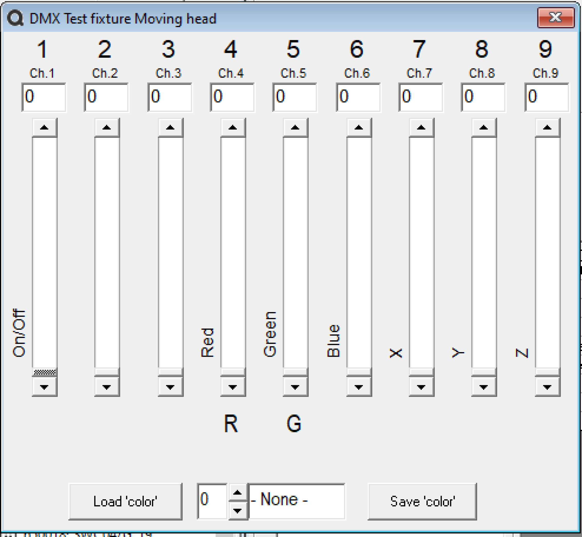
DMX controlled dimmers
In this example we are going to use a DUP-600. This is a dimmer pack with 6 channels that can be controlled via DMX. From now on we will work with 2 DMX devices.
• Device 1: DMX RGB
• Device 2: DMX Dim pack DUP600
Our RGB DMX is a lamp that continuously needs a high signal on the 4th channel to work. We can set this by selecting the I/O “** Value **” in the list of I/O’s. This is an I/O that is automatically created when creating a DMX I/O. We choose the value 255 on channel 4.
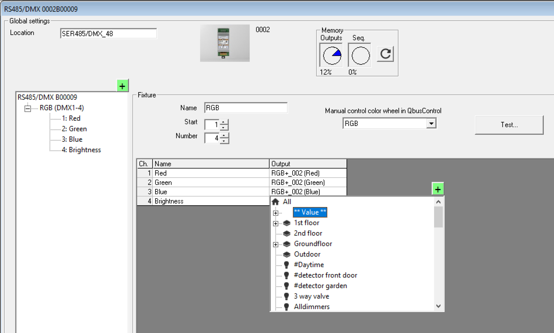
By clicking on the green + sign we can add an additional DMX lamp to our driver. The DUP-600 has 6 dim channels, so we also create 6 channels in our software. The RGB lamp uses address 1-4, so we set the DUP-600 to work from channel 5 to 10. On the I/O’s we don't put DMX mode this time, but for channels 1-5 we choose a 1Button dimmer and for channel 6 a bistable I/O.

Setting the DUP-600
By pressing the “menu” button 3 times you get to the above menu. There you can set the start channel with the Up/Down button, in our example channel 5. By confirming with “Escape” you set the dimmer that Channel 1 has DMX address 5, Channel 2 DMX address 6, etc.
By assigning different addresses you can therefore control several light points with 1 DMX module.
You can see from the red color of the DMX-LED that a DMX signal is coming in.
With the sliders you can manually control each I/O. If you do this, the DMX signal will be overruled and you will no longer be able to control this channel. To make the I/O listen to DMX you have to press the CH1 button, then the I/O takes over the set value.
